Mini-Project 1: Inverted Pendulum
Kinematics with SymPy
MCHE513: Intermediate Dynamics
Dr. Joshua Vaughan
joshua.vaughan@louisiana.edu
http://www.ucs.louisiana.edu/~jev9637/

Figure 1: Inverted Pendulum System
In this mini-project, we'll be examining the kinematics of the inverted pendulum system shown in Figure 1. Unlike many systems like this one that are used in academic environments, the main link of the pendulum in this system is not driven. Instead, the vertical rod that is free to rotate about a bearing near its base. The horizontal bar has two masses attached to its ends and is driven, relative to the top of the pinned, lower bar via a motor.
Figure 2 shows one possible way to model this system. The lower, main link of the system has mass, $m_{vert}$, and length, $l_1$. Its rotatation about a perfect pin at point $O$ is described by $\theta$. The two links are connected at point $A$. The motor driving link $BC$, which has length $l_2$, is modeled simply as a force acting at that location.
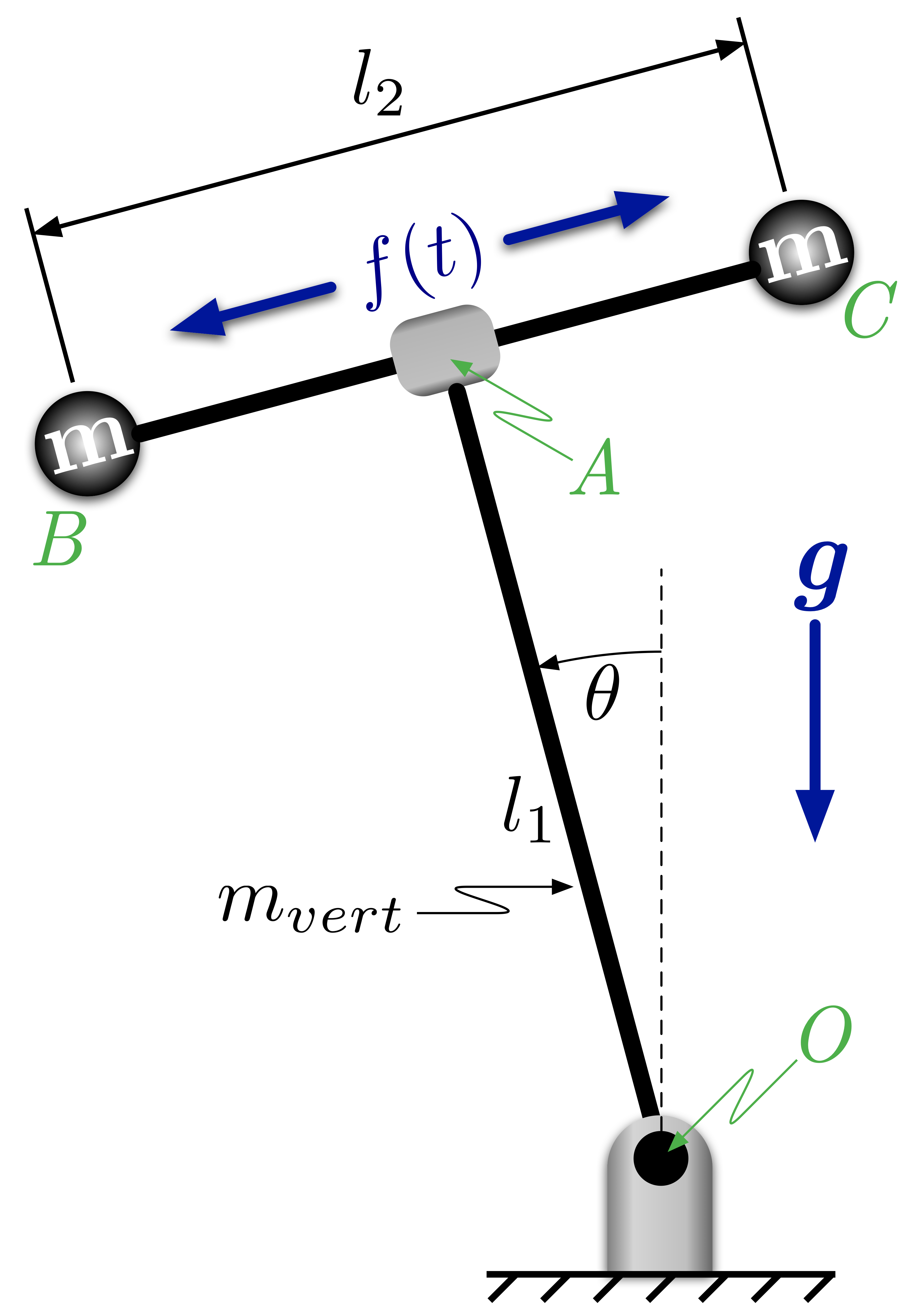
Figure 2: Inverted Pendulum Model
Assignment
For the system described above, calculate:
- Velocity and acceleration of the center of mass of the lower bar
- Velocity and acceleration of each of the two upper masses, points $B$ and $C$
- Angular velocity and acceleration of the lower bar, $OA$
- Angular velocity and acceleration of the upper, two-mass system
- Angular momentum of the lower bar, $OA$
- Angular momentum of the upper, two-mass system
Express all quantities in a fixed, Newtonian frame $N$.
Licenses
Code is licensed under a 3-clause BSD style license. See the licenses/LICENSE.md file.
Other content is provided under a Creative Commons Attribution-NonCommercial 4.0 International License, CC-BY-NC 4.0.
# This cell will just improve the styling of the notebook
from IPython.core.display import HTML
import urllib.request
response = urllib.request.urlopen("https://cl.ly/1B1y452Z1d35")
HTML(response.read().decode("utf-8"))